

Audio player docked to bottom

Listen to this article
Key takeaway
There is no single "the Duval method." Which triangle or pentagon to reach for is determined, in order, by three questions: what fluid is in the tank, what equipment produced the sample, and what you are actually trying to find out. Get those right and the method chooses itself. Mineral oil has the full toolkit; silicone has exactly one published method. And whichever diagram you use, it tells you the fault type — never the severity.
1. The reflex that misclassifies
Most practitioners reach for the Duval Triangle 1 by reflex. That is understandable — it is the primary graphical method the standard puts in front of you (IEC 60599:2022, Annex B Fig B.3), and graphical methods exist for a good reason: they classify the 15–20% of cases that the older gas-ratio methods leave with no interpretation at all (CIGRE TB771:2019, Section 2.1).
But Triangle 1 is one method in a family of more than a dozen, calibrated for mineral oil in the main tank. Apply it outside that box and it still returns a confident answer — the wrong one. The fix is not a better diagram; it is a better question. Three of them, in order.
2. First question — what fluid?
This is the most decisive branch. Mineral-oil zone boundaries do not transfer to esters or silicone, and vice versa: the gas kinetics differ, so the zone lines sit in different places (Duval 2008, p. 24; CIGRE TB443, Section 3.2). The fluid picks the toolkit before anything else.
| Fluid | Screen with | Confirm with | Refine with |
|---|---|---|---|
| Mineral oil | Triangle 1 | Pentagon 1 | Triangle 4, Triangle 5, Pentagon 2, Unified Pentagon |
| Synthetic ester (MIDEL 7131) | Triangle 3 (Midel variant) | Pentagon 3 (Midel) | Pentagon 4 / 4b, Triangle 3b |
| Natural ester (FR3, rapeseed, sunflower) | Triangle 3 (fluid variant — none for rapeseed) | Pentagon 3 (fluid variant — the first method for rapeseed) | Triangle 6 and 7 (FR3), Pentagon 4 / 4b, Triangle 3b (no rapeseed variant) |
| Silicone (PDMS) | Triangle 3 (silicone variant) | (no published silicone pentagon) | Triangle 3b (silicone variant — unpublished coordinates) |
The pattern to notice: mineral oil has the full toolkit; silicone has exactly one published method. If your fluid is anything other than mineral oil, Triangle 1 is already the wrong starting point.
Pentagon 4b and Triangle 3b share a specific trigger: reach for either only when the transformer has solid cellulose insulation and you need to tell arcing-in-paper from arcing-in-oil. Which of the two is available to you is decided by the fluid — Pentagon 4b covers rapeseed, soybean, sunflower and synthetic ester; Triangle 3b covers Midel, silicone, soybean and sunflower.
Try it yourself: the Duval Triangle tool and Duval Pentagon tool both let you pick the fluid variant before you plot, so you are working with the right zone boundaries from the first click.
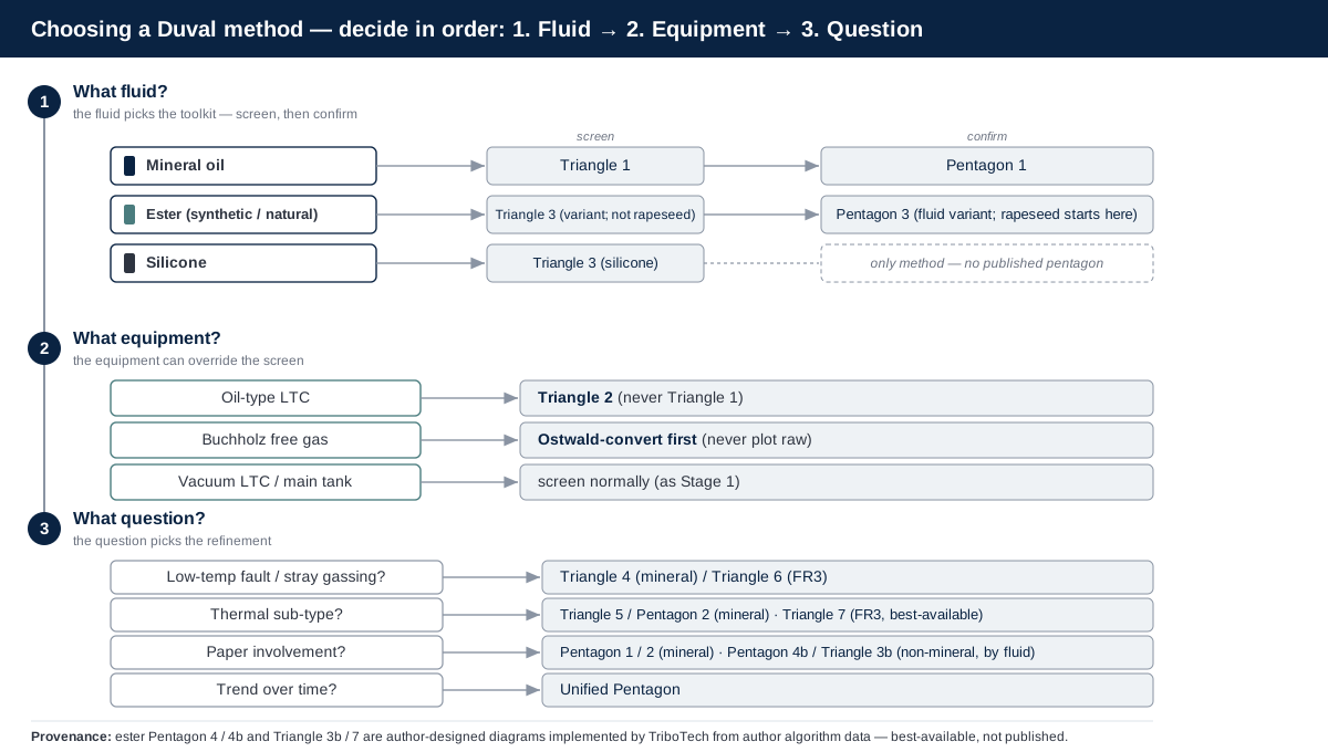
Figure 1 — The selection spine: the fluid decides the toolkit, the equipment can override it, and the question decides the refinement.
3. Second question — what equipment?
Same fluid, different equipment, different method. The classic trap is the oil-type load tap changer: normal tap-changer arcing lands squarely in the discharge zones of Triangle 1, so screening an LTC sample with Triangle 1 produces chronic false alarms. Use Triangle 2, which is built for exactly that arcing (Duval 2008, p. 22–23; IEC 60599:2022, Annex B Fig B.4). A vacuum-type tap changer, by contrast, reads like the main tank — Triangle 1 for mineral oil, Triangle 3 for non-mineral, Pentagon 3 for rapeseed ester.
One more equipment caveat that catches people out: a Buchholz relay free-gas sample can't be plotted raw. Duval diagrams read dissolved-gas ratios, so free gas from the relay must first be converted to equivalent dissolved values using the Ostwald solubility coefficients (IEC 60599:2022, Clause 7 and Table 3) — plot it before converting and the ratios, and the zone they fall in, are simply wrong. And even after conversion, treat a fast-developing fault with care: relay gas is often not yet in equilibrium with the oil, which over-represents the less-soluble gases (H₂, CO, CH₄) and can still push you to the wrong fault. For why an LTC sample must never be read like the main tank, see DGA in load tap changers.
4. Third question — what are you actually asking?
This is where method selection becomes reasoning. The screening diagram answers "is there a fault, and what type?" — but the follow-up question decides which refinement diagram earns its place.
| Your question | Start with | Sharpen with |
|---|---|---|
| Is there a fault, and what type? | Triangle 1 (mineral) / Triangle 3 (non-mineral; Pentagon 3 for rapeseed) | Pentagon 1 / Pentagon 3 |
| Stray gassing, or a real fault? | Triangle 4 (mineral) / Triangle 6 (FR3) | the Pentagon 1 stray-gassing zone |
| Which kind of thermal fault? | Triangle 5 (mineral) / Triangle 7 (FR3 — best-available, see below) | Pentagon 2 |
| Paper carbonisation? | Pentagon 2 (mineral) / Pentagon 4 or 4b (ester) | CO/CO₂ trend + furans |
| Arcing in paper, or arcing in oil? | Pentagon 1 or 2 (mineral) / Pentagon 4b (ester) / Triangle 3b (ester except rapeseed, silicone) | CO/CO₂ trend + furans |
| Is the condition changing (online monitor)? | Unified Pentagon | displacement monitoring |
The one guardrail to internalise here: the low- and high-temperature triangles are thermal sub-classifiers, not discharge tools. If your fault is a discharge (D1/D2), Triangle 4 and Triangle 5 will not resolve it — reach for a pentagon instead (IEEE C57.104:2019, Annex D.4, note a, p. 66).
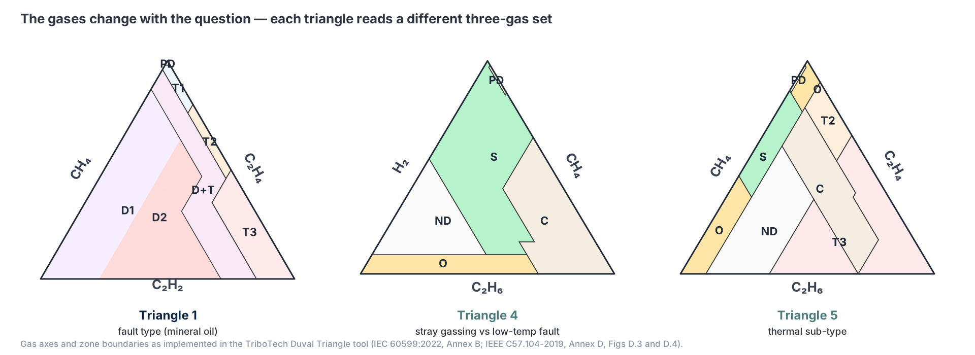
Figure 2 — Same diagram family, different gases: which three-gas set a triangle reads is chosen by the question you are asking. Gas axes and zone boundaries as implemented in the TriboTech Duval Triangle tool.
5. Triangle or pentagon — entry point vs deep-dive
Triangles read three gases and give a fast screen; pentagons read all five hydrocarbon gases and add sub-zones the triangle cannot express. The workflow is not "pick one" — it is classify with a triangle, confirm with a pentagon.
The confirmation step earns its keep even when the two agree, because when they disagree the disagreement is itself diagnostic: it can mean more than one fault is developing at once (CIGRE TB771:2019, App H.4 & H.6). For a worked pass through the two together, see inside Duval Triangle 1 and Pentagon 1. If you want the geometry under the hood, how Duval diagrams are constructed derives it.
6. What Duval never tells you
Every Duval diagram normalises the gases to percentages before it plots them — and normalisation throws away all absolute-concentration information. A trace reading and a severe one can plot at the same point in the same zone. Duval classifies the fault type; it says nothing about severity. To decide whether a clean zone hit is routine or an emergency, you still need the absolute levels and the rate of change (IEEE C57.104:2019, Tables 1–4, p. 38–39). For how the IEC, IEEE and CIGRE frameworks fit around the Duval methods, see navigating the DGA maze.
Three mis-selections account for most of the wrong answers we see, and this guide has now covered all three: Triangle 1 on an ester or silicone fill; Triangle 1 on an oil-type tap changer; and a low-/high-temperature triangle pressed into service on a discharge fault.
7. The ester frontier
The ester toolkit is growing, but it is younger than the mineral-oil one, and honesty about that maturity matters. Triangle 3 (Duval 2008; CIGRE TB 443) and Pentagon 3 (Duval & Lamarre 2017) are the published core for esters, and they already carry more than they are usually credited with — the published Pentagon 3 figures include a stray-gassing zone, so nothing downstream has to add one.
What the later diagrams add is narrower than it looks. Pentagon 4 re-labels Pentagon 3's thermal zones — O, C and T3-H over the same polygons, at the same 40% summit — so an ester thermal fault can be reported in the same vocabulary as mineral-oil Pentagon 2. That buys cross-fluid comparability, not extra resolution. Pentagon 4b is where the real additions sit: it carves arcing-in-paper (D1-P/D2-P) out of the D1 and D2 zones, and corrects the summit to 33.333%. Triangle 3b does that same one thing on ternary axes — Triangle 3 plus the paper-versus-oil arcing split, with its partial-discharge, mixed-fault and thermal zones all left vertex-identical.
The two are complements, not alternatives, and the difference is fluid coverage. Pentagon 4b carries the split for rapeseed, soybean, sunflower and synthetic ester, but not silicone; Triangle 3b carries it for Midel, silicone, soybean and sunflower, but not rapeseed. On a rapeseed fill only Pentagon 4b can answer the paper-versus-oil question; on a silicone fill only Triangle 3b can.
The split itself is a published, peer-reviewed method — Duval and Buchacz established it for mineral oil (2022). What is unpublished is the ester geometry of the split, and for the pentagons it runs deeper than the refinements: the published ester Pentagon record is graphical — figures with zones but no numbers — and CIGRE TB771's own pointer for numerical values (CIGRE TB771:2019, App H.8, p. 72) leads back to that same figures-only paper. Every ester Pentagon coordinate we implement therefore comes from the authors' unpublished algorithm files, Pentagon 3's included. The diagrams themselves are not ours — Pentagon 4 and 4b are the authors' own worksheet designations, Triangle 3b the author's own document title, Triangle 7 CIGRE's name — but our implementation of them is best-available rather than standardised, peer-reviewed geometry. Triangle 7, the ester thermal-refinement triangle implemented for FR3, traces to a separate author workbook rather than to those ester files; its publication record stays genuinely ambiguous, but its boundaries are machine-verified against that workbook, so the ambiguity sits in the paper trail rather than in the numbers.
Practically, that means two things. Treat an ester paper-fault call as a lead to corroborate — with CO/CO₂ trend and furans — not as a settled verdict. And expect the ester diagrams to keep tightening: a coordinate-alignment refresh of the ester geometry is an active work item as the underlying algorithm data matures.
8. A three-question checklist
Before you plot anything, answer these in order:
- What fluid? Mineral oil → Triangle 1 family. Ester or silicone → Triangle 3 variant, except rapeseed ester → Pentagon 3. This decides the toolkit.
- What equipment? Main tank or vacuum LTC → screen normally. Oil-type LTC → Triangle 2. Buchholz free gas → convert to dissolved-equivalent via the Ostwald coefficients (IEC 60599:2022, Clause 7 + Table 3) before plotting — never plot it raw.
- What am I asking? Fault type → screen with a triangle, confirm with a pentagon. A low-temperature fault or stray gassing, the thermal sub-type, or paper involvement → the matching refinement diagram. Trend over time → the Unified Pentagon.
Then remember the diagram gives you the type, and you supply the severity from the absolute numbers.
Put it to work: pick your fluid and plot your gases in the Duval Triangle and Duval Pentagon tools, or run the full picture — classification plus trend — in the Unified DGA dashboard. If a result is ambiguous or the methods disagree, get in touch and we will read it with you.
Frequently asked questions
Which Duval triangle should I use for my transformer?
What is the difference between the Duval Triangle and the Duval Pentagon?
Can I use the Duval Triangle 1 on an ester-filled transformer?
Which Duval method works for silicone transformer oil?
Does the Duval Triangle tell me how serious the fault is?
Why does my Duval Triangle result disagree with the Pentagon?
Standards referenced
The methods on this page are anchored in these standards — follow each into our standards library.
Put Theory into Practice
Try our interactive Duval diagnostic tools or use our new unified workflow to analyze your transformer oil data.