Audio player docked to bottom
Listen to this article
Key takeaway
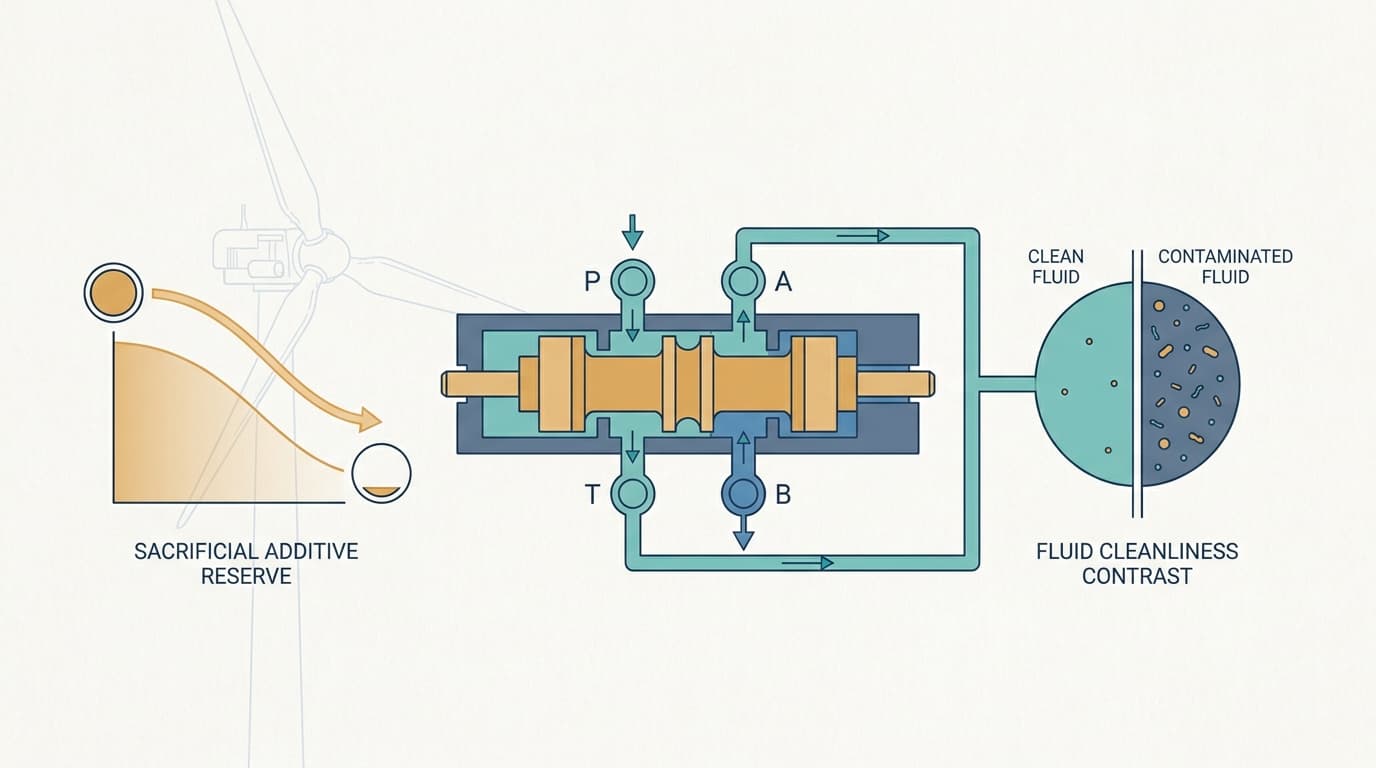
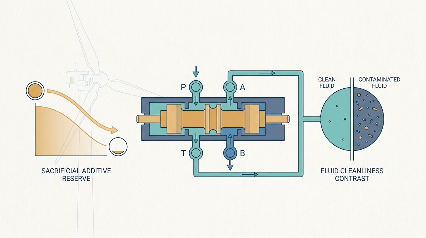
On a zinc-based ZDDP hydraulic oil, the two signals that decide the oil change are additive depletion and particle count — not base-oil oxidation. Voltammetric monitoring reads the ZDDP anti-wear additive together with the phenol and amine antioxidants in one trace, trended against the oil's own new-oil baseline; the particle count tells you how clean the fluid is. In our field experience on wind-turbine pitch hydraulics, the base oil rarely degrades to poor values before one of these two has already called the change. Two practices make the pair trustworthy: confirm a high automatic particle count by our standard automated optical-microscope membrane count (ISO 4407:2025) before believing it, and fit offline filtration so the count has a chance to stay low. Zinc-free fluids remove the direct additive handle and reopen a real monitoring gap — covered honestly below.
What is in a hydraulic oil
The ISO 6743-4 classification is built like a ladder, each rung adding one more layer of protection:
- HH — bare mineral oil, no additives.
- HL — adds rust and oxidation inhibition.
- HM — adds anti-wear protection. This is the workhorse industrial hydraulic fluid, sold in Europe under the DIN designation HLP.
- HV — adds a viscosity index improver for wide temperature ranges.
(The corresponding minimum-requirements specifications are ISO 11158 and DIN 51524-2.)
A classic HM/HLP package is compact: a hindered phenol antioxidant, often paired with an aromatic amine; ZDDP as the anti-wear additive — which also acts as a secondary antioxidant; a rust inhibitor and a copper passivator; a silicone antifoam. HV adds the VI improver polymer on top — and because that polymer shears down in service, an HV oil has to be watched at both 40 °C and 100 °C, not at 40 °C alone, so that a quiet loss of high-temperature viscosity is not missed. Compared with a gear oil the package is smaller and the loads gentler, but the system is often more sensitive to what the additives leave behind, because servo and proportional valves operate on clearances that do not forgive deposits — or contamination.
This article stays with mineral HM/HLP/HV oils. Ester-based fire-resistant (HFDU) and environmentally-acceptable (HEES) hydraulic fluids are a different monitoring world — governed by hydrolytic acid-number rise rather than by the additive signals discussed here — and are out of scope.
The two signals that decide the oil change
On a zinc-based ZDDP hydraulic oil, two condition parameters do the work of deciding when the oil has reached the end of its useful life: the additive depletion trend and the particle count. Base-oil oxidation matters and is monitored — but in our field experience it is not usually what calls the change first.
Voltammetric monitoring is TriboTech's standard reading on the additive side. The method runs a linear-sweep voltammogram in a neutral test solution and reads, in one trace, the sacrificial additives as they deplete: the ZDDP anti-wear peak together with the hindered phenol and aromatic amine antioxidants, each trended as percent remaining against the oil's own new-oil baseline. The standards basis is ASTM D4378-24 §9.2.2.2, which states that voltammetry can measure phenols, amines, and ZDDP against a product-type baseline. This is comparative, baseline trending — read against the oil's own baseline at the same laboratory, never a number lifted from a spec table. The mechanics, the per-class depletion logic, and the 25 % remaining-useful-life alarm are covered in our RULER deep dive, which walks through how additive depletion and oxidation reserve are read off a single live trace.
The particle count is the second leg. It tells you whether the fluid is clean enough for the clearances it has to pass through — and on a servo or proportional-valve system, cleanliness is not a comfort metric, it is a functional requirement.
Our field experience: additive and dirt lead, oxidation lags
This is field experience, not a law. Across the wind-turbine hydraulic pitch systems we monitor, we rarely see the base oil degrade to poor values before either the additive package has depleted or the particle count has become unacceptable. The fluid is usually still serviceable as a base oil when one of the other two signals has already called the change.
The reason is practical rather than chemical. Most of these systems run without offline filtration (more on that below), so particle contamination has no continuous cleanup quietly resetting it; and the sacrificial additives are, by design, consumed before the base stock is. So additive depletion and particle count are the live end-of-life drivers, and base-oil oxidation is the lagging indicator — not the trigger. A programme that watches oxidation hardest is watching the slowest hand on the clock.
One caveat travels with the voltammetric signal. The fully validated voltammetric test methods are scoped to non-zinc turbine oils; their application to a ZDDP hydraulic oil rests on the ASTM D7590 guide, not on those test methods, and no standard sets a "percent ZDDP remaining" condemnation limit. ZDDP appears only once in all of D4378. So it is a powerful, real, routine trend — and it is a guide-level application read against the oil's own baseline, never a spec-table threshold.
Confirming the particle count
Here is the practice that separates a defensible cleanliness number from a misleading one. TriboTech never reports a high automatic particle count without confirming it on a membrane filter patch under an optical microscope — physically seeing and identifying the particles. The automatic counter alone is not enough.
Automatic particle counters work by light extinction, the method standardised in ISO 11500:2008: a particle passing through a beam blocks light, and the size of the shadow is converted to a particle size and tallied. The method is fast and reproducible, but its physics carry blind spots that a hydraulic fluid routinely walks into. The technique counts single particles in "clear, homogeneous, single-phase liquids" (ISO 11500:2008, Clause 1, p. 1) — and a field hydraulic sample is often none of those things:
- Air bubbles and water droplets read as particles. "The presence of a fluid interface obstructs the light beam and gives false signals" (ISO 11500:2008, Clause 1, NOTE 2, p. 1). Entrained air and free water are interfaces; the counter cannot tell them from solids.
- Wet or cloudy fluid voids the count. A cloudy or free-water-bearing sample "shall not be counted" (ISO 11500:2008, Clause 6.5.2, p. 5), and if water affects the count the sample "shall not be evaluated" (Clause 6.5.4.3, p. 7). An automatic count run on a wet field sample reports a number the standard itself does not sanction.
- High concentration distorts the size distribution. When particles are dense, two small ones in the beam together read as one large one — coincidence error (ISO 11500:2008, Clause 7.3.7, p. 11; coincidence limit defined Clause 3.2, p. 2; the run should stay below 80 % of the coincidence limit, Clause 6.4.1, p. 4). The effect is directional: the counter over-counts the large sizes and under-counts the small — it does not simply read high.
- Soft contaminants are undersized. Soft, gel-like, or semi-transparent contaminants pass less of a shadow than a hard particle of the same size, so the counter sizes them too small [our experience].
The common thread is that the automatic counter misjudges the count — sometimes high, sometimes low, sometimes in the size distribution rather than the total. This is a property of the light-extinction principle, so it applies whether the counter is an online sensor or a bottle-sample bench instrument; both share the blind spot.
The method TriboTech actually trusts on the cleanliness side is automated optical-microscope membrane counting (ISO 4407:2025) — an optical microscope reading a membrane filter patch, with image-analysis software performing the detection, size classification, and counting. This is our standard particle-counting method: we run it on all gear oils, on many hydraulic oils, and on grease-lubricated components too, and we run it on every hydraulic sample whose automatic count comes back high. The automatic light-extinction counter is the fast screening step; the automated microscopy is the method we verify the high reading against before we believe it.
The physical principle is what gives it the edge. The fluid is filtered through a membrane and the retained particles are imaged, sized by their maximum Feret diameter, and identified — so the method physically distinguishes a fibre (formally a particle over 100 µm with a length-to-width ratio of at least 10:1) from a fatigue chip from a water artefact, which a light-extinction counter cannot do at all.
The optical imaging also carries useful information about what the debris is. ISO 4407:2025 provides incident- and transmitted-light imaging; the metal-versus-non-metal call we make from that image is our own analyst practice, not a classification the standard defines. Under incident light a metallic particle tends to be opaque and reflective, so reflectivity helps tell wear metal apart from external contamination — the difference between a system shedding its own bearings and one simply taking in dirt. It is a help, not a guaranteed two-bucket sort: dark non-metallics such as carbon, seal debris, or magnetite are also opaque, and oxidised or heat-tinted steel loses its bright reflectivity — so the reflectivity read is judged alongside the rest of the image, never on its own.
It remains a laboratory membrane method — filtration and a microscope, not an inline real-time sensor — but it is automated and non-subjective, not a manual fallback, and it sizes to within about one ISO 4406 code. Both methods can be expressed as an ISO 4406:2021 cleanliness code, but the automatic count (three numbers) and the microscope count (two numbers) are built differently and are not directly interchangeable — so when the patch confirms or corrects an automatic count, we report which method produced the figure.
Confirming the count tells you how dirty the fluid is; the next question is what keeps it from getting that dirty in the first place.
Offline filtration: the case for fitting it
If particle count is one of the two signals that ends an oil's life, then keeping the count low is one of the highest-leverage things an operator can do — and the tool for that is offline (kidney-loop) filtration: a low-flow filtration circuit that continuously cleans the reservoir in parallel with the main hydraulic circuit.
The before-and-after evidence is, in our experience, day-and-night. We see contaminated systems where the count is dragging the oil toward an early change, and after an offline loop is fitted the same system holds a clean count for far longer. We can find no good engineering argument against pre-installing offline filtration on a hydraulic pitch system. Where it is absent, the reason is almost always historical: a CAPEX decision taken when the turbine was specified, when the filtration circuit looked like a cost to trim rather than an asset to fund.
That is the wrong frame over the life of the machine. This is a lifecycle-cost judgment, not a quantified guarantee — but the direction is not in doubt: the small added capital cost of an offline loop pays back many times over the turbine's life in reduced downtime, lower service and maintenance cost, and — offshore especially, where every oil change is a vessel mobilisation — fewer oil changes. Retrofit pays off too, and the earlier in the asset's life it is fitted, the more of that life it protects.
One condition makes the case hold: the additive package has to be monitored alongside. Offline filtration keeps the fluid clean, but it does not regenerate the sacrificial additives — and a clean oil with a depleted additive package is still at the end of its useful life. Fit the filtration, and watch the additive trend, and the two together extend the oil's serviceable life in a way neither does alone.
Where TriboTech sits on the retrofit question is worth stating plainly: we do not sell or install offline-filtration hardware. So when an owner is weighing whether to fit a loop, we are the neutral party — we can build the lifecycle-cost model (downtime, service and maintenance, oil-change avoidance, and offshore the vessel mobilisations behind each change), define the technical specification for the filtration circuit, provide owner's-engineering support through the decision, and project-manage the retrofit itself. Because we have no filtration product in the deal, the recommendation carries no conflict of interest. Whether to fit a loop and how to specify it is purely a question of the asset owner's economics and the system's condition.
Re-additivation on hydraulic systems: a different risk than gear oil
Monitoring the additive package raises its own question: when the trend says the additive is depleting, can you put it back rather than change the oil? When the additive trend, rather than contamination, is what is running the oil toward a change, replenishing the additive — a top-treat rather than a full drain and refill — is in principle an option, and commercial re-additivation products exist for hydraulic fluids. But the hydraulic case is not the gear-oil case, and the difference is one of who stands behind the practice.
On large-volume gear and circulating systems, re-additivation is becoming a supplier-acknowledged option: oil suppliers have begun to advise it as an alternative to a full oil change, and the supplier position is moving toward it. On hydraulic systems that backing is not there. Suppliers generally do not endorse re-additivating a hydraulic fluid, and the reasons are real — the deposit sensitivity of servo and proportional valves, additive-balance and solubility limits, and smaller reservoir volumes that leave little margin for a dosing error. So the risk profile is genuinely different: on gear oil there is a supplier-backed path; on hydraulic there is not.
Our position is to advise it case by case. Where a hydraulic system is a strong candidate and the asset economics justify it, re-additivation can be examined on its own merits — dosed by analysis, supplier- or lab-controlled, re-tested afterwards, never poured in blind — but the absence of supplier backing is part of the risk an operator takes on, and we say so. For most hydraulic fleets the defensible default remains a change-out when the voltammogram and the confirmed particle count say so.
Zinc-free hydraulic oils: the monitoring gap, stated honestly
A growing share of hydraulic fluids are formulated without zinc — ashless anti-wear chemistry, using organic phosphates, phosphites, and amine phosphates instead of ZDDP. The drivers are environmental (zinc is a wastewater problem) and technical (deposit sensitivity in servo valves; in some silver-coated bearing applications ZDDP is held to be aggressive toward the silver surface). The replacement chemistry protects well. The monitoring consequence is a real gap, and it is worth stating plainly rather than papering over.
Going zinc-free removes the direct additive handle that makes the ZDDP programme above so clean. The voltammetric ZDDP peak is gone, and so is the zinc element trend. What is left for the anti-wear additive is total phosphorus by ICP — an atom count, not molecular condition: a phosphite that has hydrolysed into phosphoric acid still contains exactly as much phosphorus as the day it was blended, while its anti-wear function is gone. No routine method measures organic anti-wear activity directly; there is no ashless equivalent of the ZDDP peak. Voltammetry does not vanish on an ashless oil, but with no ZDDP to read it reports only the phenol and amine antioxidants the fluid carries — antioxidant health, never the anti-wear additive.
The recognised sentinel for ashless anti-wear depletion is therefore rising acid number together with elevated water — not a falling phosphorus trend. Organic phosphate and phosphite additives deplete by hydrolysis, and water accelerates it; the acidic degradation products show up as acid number long before the phosphorus moves. ICP total phosphorus does not fall on hydrolysis until the degraded species physically leave the oil — adsorbed, filtered out, or laid down as varnish — so a declining phosphorus trend is a late, secondary confirmation, not the early warning. Read water and acid number together as the leading pair; treat a falling phosphorus trend as confirmation after the fact. On these oils the particle-count discipline above matters just as much — the cleanliness signal is independent of the additive chemistry.
Two special programmes: RPVOT and ³¹P-NMR
Neither of the two leading signals — the additive voltammogram and the particle count — is displaced by what follows. Two further tests sit deliberately outside the routine programme: they are not competing primary triggers but brought-in tools, run as special programmes when a specific case earns them, never on every sample.
RPVOT (ASTM D2272) is the one integrated oxidation-reserve reading available — it folds the phenol, the amine, and any synergistic contribution from the anti-wear package into a single number, which makes it valuable, especially on an ashless fluid where the direct additive signals are scarce. But it is a periodic corroboration of the additive trend, not a co-equal end-of-life trigger: oxidation reserve is the lagging hand on the clock, and RPVOT reads it against the new-oil baseline rather than calling the change in its own right. And on used oil the result is distorted — RPVOT runs over a copper catalyst, so dissolved wear metals push the reading, and antioxidant-breakdown intermediates skew it further; it is least repeatable exactly near end of life. So it is run periodically as a deliberate reserve check, brought back in when the antioxidant trend approaches its alarm, not as a routine trend.
Phosphorus-31 NMR is the method that resolves what ICP cannot on an ashless oil: it distinguishes the intact organic-phosphorus additive from its hydrolysed and oxidised degradation products — molecular condition, not just total phosphorus — which is exactly the reading the ashless gap is missing. There is no ASTM or ISO standard method for in-service lubricant ³¹P-NMR; it is not accredited, not routine, and not fast. TriboTech offers it as a special programme, exactly parallel to how RPVOT is a deliberate non-routine reading — accessed through specialist capability when a specific case justifies the cost and turnaround, not a line on a standard report.
What to take away
- On a ZDDP oil, the additive voltammogram and the particle count are your two leading end-of-life signals. In our field experience the base oil rarely reaches poor values before one of these has called the change. Trend the ZDDP peak with the antioxidants against the oil's own baseline.
- Never trust an automatic particle count alone. Confirming a high count by automated optical-microscope membrane counting (ISO 4407:2025) is our standard practice. Light-extinction counters misjudge — air, water, high concentration, and soft contaminants all bias the result, and the standard does not sanction a count on a wet sample.
- Fit offline filtration, and fit it early. Pre-install on new pitch systems, retrofit on existing ones. The CAPEX is small against the lifecycle saving in downtime, maintenance, and — offshore — oil changes. It only delivers if the additive package is monitored alongside — and because we sell no filtration hardware, we can model the retrofit case as the neutral party.
- Re-additivation is case-by-case on hydraulic, and the risk differs from gear oil. Suppliers back it on gear/circulating systems; they generally do not on hydraulic. Default to change-out unless the economics and the system make a strong case.
- On a zinc-free oil, expect a gap and manage around it. ICP reads total phosphorus, not molecular condition; watch water and acid number together as the hydrolysis sentinel; treat a falling phosphorus trend as late confirmation.
- Treat RPVOT and ³¹P-NMR as special programmes — deliberate, non-routine readings brought in when a case earns them, not checkboxes on every sample.
The same scope honesty that applies to gear oils applies here — the voltammetric test methods are formally turbine-oil methods, and the D7590 guide is the documented bridge; the full argument is in our gear-oil companion piece. If your hydraulic fleet is running on a monitoring programme that watches oxidation hardest and leaves the particle count to an unconfirmed automatic number, that is exactly the kind of gap we help close: get in touch.
Standards referenced
The methods on this page are anchored in these standards — follow each into our standards library.
Put Theory into Practice
Try our interactive Duval diagnostic tools or use our new unified workflow to analyze your transformer oil data.