
Audio player docked to bottom

Listen to this article
Key takeaway
Viscosity is the single most-quoted lubricant property, and the most misread. Three things are worth holding apart. Test methods (ASTM D445, D7042, D7483) measure viscosity; they set no pass/fail limit. The Viscosity Index (ASTM D2270) describes how viscosity changes with temperature between 40 and 100 °C — it is a design variable, not a quality score, and it says nothing about oxidation stability, additives, or the actual viscosity level. ISO VG (ISO 3448) is the procurement shorthand for viscosity at 40 °C, and it is orthogonal to VI: a VG 32 oil can have a VI of 95 or 160. Read every viscosity number with its measurement uncertainty.
1. Start with the intuition
Everyone has a working sense of viscosity before they meet the word. Water runs off your hand; honey clings to the spoon. Cold honey is worse than warm honey — it barely moves. That last observation matters more than it looks, because it carries the whole story: viscosity is resistance to flow, and it depends on temperature.
In a machine, that resistance is not a nuisance — it is the job. The oil film in a bearing or a gear mesh has to be thick enough to keep two metal surfaces apart under load, and thin enough not to waste energy churning. The viscosity of the oil is what sets that balance. Too thin and the film collapses; too thick and the machine fights the oil. So before any units appear, fix the idea: viscosity is the property that carries load and separates surfaces, and it is not a constant — it falls as the oil heats up.
2. Two viscosities, one relationship
There are two viscosities, and the difference is physical, not a choice of method.
Dynamic viscosity (η) is the "ratio between applied shear stress and rate of shear at a given temperature" (ASTM D7483-21, §3.1.2, p. 2). Its unit is the millipascal-second (mPa·s, formerly the centipoise, cP) (ASTM D445-24, §1.4, p. 1). It is the viscosity that matters when a force drives the flow — a pump pushing oil, a loaded bearing shearing a film.
Kinematic viscosity (ν) is the "ratio of dynamic viscosity to density at a given temperature; a measure of resistance to flow of a liquid under gravity" (ASTM D7483-21, §3.1.3, p. 2). Its unit is mm²/s (formerly the centistoke, cSt) (ASTM D445-24, §1.4, p. 1). It is what you get when gravity alone drives the flow.
The two are tied by a single relation:
kinematic viscosity equals dynamic viscosity divided by density (ASTM D7483-21, §14, p. 5; ASTM D445-24, §14.2, Eq. 3, p. 8, in the inverse form ).
This is the rung most lubricant content gets vague on. Dynamic and kinematic viscosity are not "two methods" or two units for the same thing — they are two physical quantities linked by density. Industrial lubrication work quotes the kinematic viscosity in mm²/s, at the two universal reporting temperatures of 40 °C and 100 °C, because the capillary reference method measures gravity-driven flow directly and those two temperatures are the basis for the Viscosity Index (ASTM D2270-24, §1.1, p. 1). Dynamic viscosity comes back into play whenever a force, not gravity, is driving the film.
3. Why tribology cares
Viscosity determines film thickness, load-carrying capacity, friction losses, and heat dissipation — which is why it is the first property an asset manager looks at when an oil is in question.
Qualitatively, the lubrication regime a component runs in depends on whether the oil can build a film at the speed, load and temperature it sees. When the film is thick enough to keep the surfaces fully apart, friction is low and surface-to-surface wear is essentially eliminated — though fatigue mechanisms such as rolling-contact fatigue and micropitting can still develop even under a nominally adequate film, which is a routine finding in wind-turbine gearboxes. As the film thins — at low speed, high load, or high temperature — the surfaces begin to touch at their high points, friction rises, and wear starts. Push it further and you reach metal-to-metal contact. The opposite failure is just as real: an oil that is too viscous for the duty wastes energy churning and runs hot.
The practical consequence for condition monitoring is direct. Viscosity at 40 °C is the first parameter we check in gear-oil and hydraulic-oil monitoring, because it answers two questions at once: is the correct lubricant in the system, and has the bulk oil degraded or been contaminated. A viscosity that has drifted off its grade is rarely a small problem — it is usually the headline finding, with the cause (wrong top-up oil, fuel or solvent ingress, oxidative thickening) waiting underneath.
The relationship between lubrication regime and operating conditions was first mapped by Richard Stribeck in his journal-bearing experiments at the turn of the twentieth century. The friction-speed characteristic carries Stribeck's name in large part because Gümbel summarised Stribeck's results into a single curve. The group on the x-axis was later compressed by Mayo Hersey into a single dimensionless number — the Hersey number, ηN/P, viscosity times speed divided by load (textbooks also call the same group the Stribeck number, written ηU/W). Plotting friction against this number gives the Stribeck curve. At low Hersey number the surfaces run in boundary lubrication: asperities carry the load and friction is high. As the number rises, the contact passes through mixed and elastohydrodynamic regimes into full hydrodynamic film, where friction reaches a minimum before climbing again as viscous churning takes over.
What sets the regime quantitatively is the film parameter λ — the film thickness divided by the combined surface roughness of the two surfaces. Below about λ ≈ 1 the surfaces are sliding on each other; above about λ ≈ 3 they are effectively fully separated. The Stribeck curve is the friction view of that same transition.
The reason viscosity is the first lubricant property an engineer reaches for is written into the x-axis: it sits in the numerator. Raise the viscosity, raise the speed, or unload the contact, and you move to the right — toward a thicker, safer film. That is also the tribological reason a viscosity index matters rather than being a datasheet curiosity: a high-VI oil holds the operating point further to the right across the temperature range, so the machine stays in full film as it heats up. And the friction minimum is not the sweet spot to design for. Large bearings are deliberately sized to sit to the right of the minimum, with margin — because a shock load or a temperature spike at the minimum drops the contact straight into mixed or boundary lubrication, and film collapse is very hard to recover from. The small extra viscous loss is the price of that safety margin. That is the whole tribological argument for why viscosity matters, in one curve.
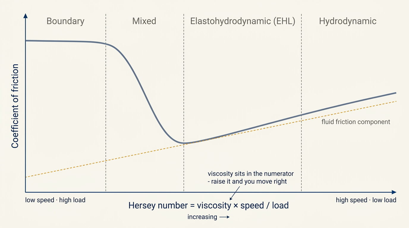
We show the classic curve shape only. The exact position of the regime boundaries depends on surface finish, geometry and duty, and cannot be drawn as universal numbers — the principle, that too thin fails by contact and too thick fails by loss, is what carries across every application.
4. How viscosity is measured
Three method families cover almost all industrial viscosity work, and they trade precision against convenience in ways worth knowing before you compare two numbers.
Capillary — the reference method (ASTM D445 / ISO 3104). A fixed volume of oil flows under gravity through a calibrated glass capillary, and you time it; the kinematic viscosity is the flow time multiplied by the capillary constant, (ASTM D445-24, §14.1, Eq. 2, p. 8). Two determinations are made and averaged, with a minimum manual flow time of 200 s (ASTM D445-24, §10.2, p. 6). This is the referee method — when two methods disagree, the D445-derived value is the one that is accepted (ASTM D2270-24, §1.3.1, p. 1). It is also the most precise: for formulated oils the reproducibility is about 1.2 % at 40 °C (R = 0.0122x, ASTM D445-24, §17.2.2, p. 10).
Stabinger — rotational with simultaneous density (ASTM D7042). A single injection of ≥5 mL measures dynamic viscosity and density at the same time, and the kinematic viscosity is calculated as ν = η/ρ (ASTM D7042-25, §1.1 + §4.1, p. 1). Its appeal is the small sample and the free density value. Against the D445 reference, the kinematic bias for base oils is 0.998·X at 100 °C and 1.000·X at 40 °C — smaller than D445's own repeatability, so for base oils it is insignificant; formulated oils use the standard's correction table (ASTM D7042-25, §X1.1–X1.2 + Table X1.1, pp. 11–12).
Oscillating piston — field-portable (ASTM D7483). A magnetically driven piston is timed in a stainless-steel chamber to give dynamic viscosity, from which kinematic viscosity is derived (ASTM D7483-21, §4.1, p. 2). It handles opaque oils and runs automatically, which makes it a good screening and trending tool. But its precision is far wider — reproducibility is on the order of 17 % at ~200 mPa·s (ASTM D7483-21, §16.1.2, p. 5) — so it is not a substitute for a capillary result when a number has to stand up.
The reporting rule applies to all of them: D445 reports kinematic viscosity to four significant figures, with the test temperature (ASTM D445-24, §15.1, p. 8). A viscosity value without its temperature is not a result. This is the single most common omission in vendor and trade-press content, and it is the reason a "viscosity of 46" tells you nothing until you know whether it is at 40 °C or 100 °C.
For the curious — cold-climate viscosity. For mineral insulating oil at very low temperature, IEC 61868 adapts the capillary method with a 20-hour cold soak to capture the non-Newtonian wax behaviour that develops near the pour point, and reports a dual result (IEC 61868:1998, §7.4 + §8.1.2, pp. 15–19). It is a specialised branch of the capillary family, relevant to Nordic transformer installations.
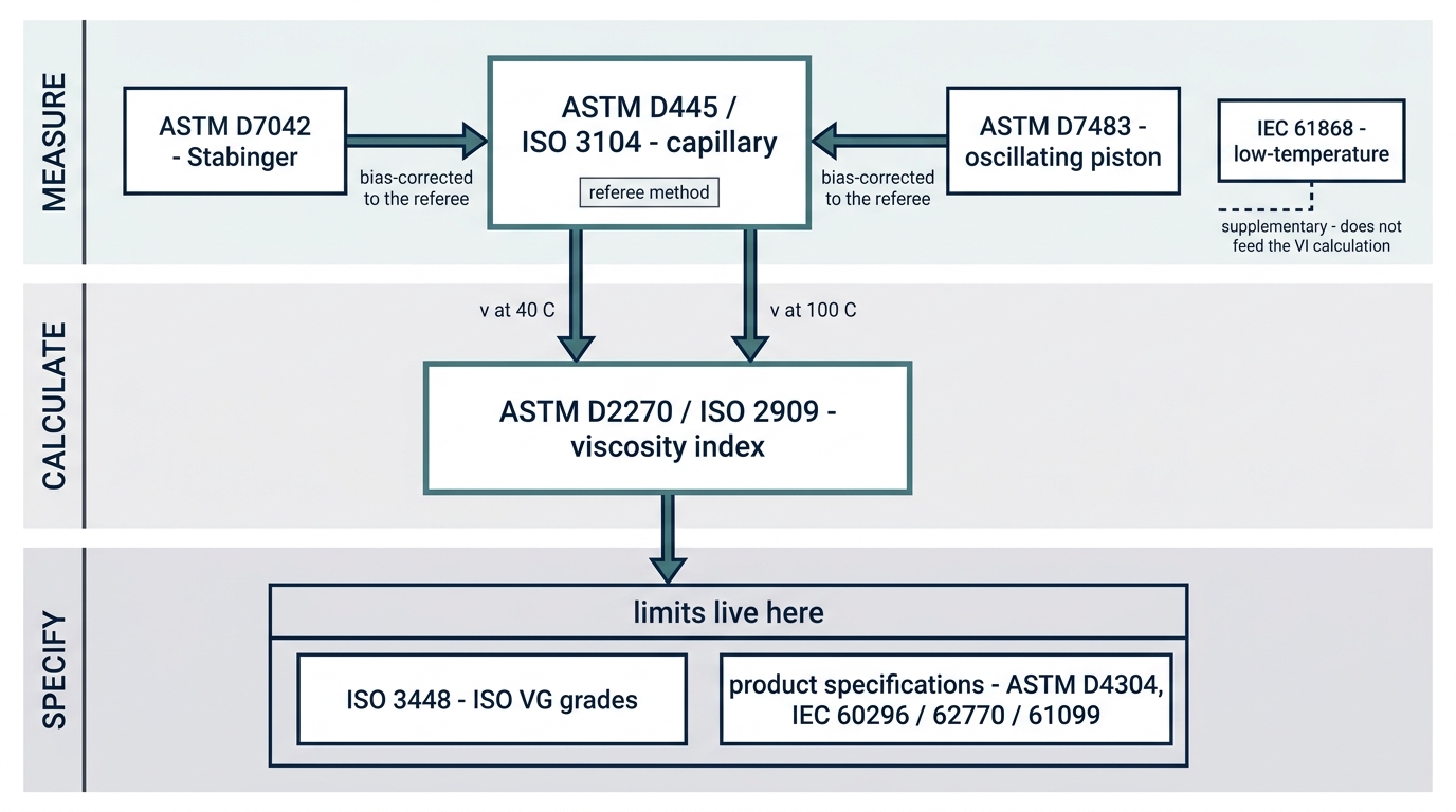
That figure carries the structural point of this whole article: none of these test methods sets an acceptance limit. D445, D7042, D7483 and D2270 all specify how to measure or calculate, never a pass/fail value — as a test method, D7042 sets no acceptance limit, because its scope is measurement, not specification (ASTM D7042-25). Acceptance limits live in the product or maintenance specification: ASTM D4304 for turbine oils, and IEC 60296 (mineral oil), IEC 62770 (natural ester) and IEC 61099 (synthetic ester) for transformer fluids, each of which sets a viscosity limit at 40 °C. When you compare a result against a limit, the limit comes from the spec, not from the test method.
5. Why viscosity falls with temperature
Heating an oil reduces the cohesion between its molecules, so it flows more easily — viscosity drops as temperature rises. This is why the reporting rule in §4 exists: a viscosity number is meaningless without its temperature.
The shape of that fall — the viscosity-temperature curve — can be linearised. For petroleum oils and liquid hydrocarbons, the relationship plots as a straight line on the special charts of ASTM D341 (the MacCoull relationship), so that if you know the viscosity at two temperatures you can read it off at a third within a limited range (ASTM D341-20(2025), §1.1 + §4.1, p. 1). A worked example from the standard makes this concrete: a fluid measured at 70,0 mm²/s at 40 °C and 10,0 mm²/s at 100 °C has a calculated kinematic viscosity of 22,3 mm²/s at 70 °C (ASTM D341-20(2025), §5.2–§5.3, p. 5). That is exactly the question a reliability engineer asks when the lab reports 40 °C and 100 °C but the bearing actually runs at 70 °C.
Two cautions travel with this. First, fluids other than hydrocarbons "will usually not plot as a straight line" on the D341 charts (ASTM D341-20(2025), §3.1, p. 1). That wording is worth reading precisely. Ester fluids are built on hydrocarbon chains, but the ester group carries oxygen — chemically they sit outside the strict hydrocarbon class the charts were derived for. In practice a natural or synthetic ester often runs close to linear over a working range, yet the linearity is no longer guaranteed by the standard: interpolation between two measured points is usually serviceable, extrapolation beyond them is where the assumption quietly fails. Verify against a measured point before relying on it. Second, for extrapolation the two known points must be far apart, or experimental error in the measurements and in drawing the line seriously degrades the estimate (ASTM D341-20(2025), §4.3, p. 5).
The Viscosity Index is a compressed version of this same curve — it summarises the slope between 40 °C and 100 °C into one number. It is not a model of viscosity at every temperature, and that limit becomes the next misconception worth dismantling.
6. The Viscosity Index
The Viscosity Index is "an arbitrary number used to characterize the variation of the kinematic viscosity of a petroleum product with temperature" (ASTM D2270-24, §3.2.1, p. 2). For oils of similar kinematic viscosity, a higher VI means a smaller effect of temperature (ASTM D2270-24, §3.2.1.1, p. 2). A high-VI oil holds its viscosity better across the operating range; a low-VI oil thins out more as it heats.
Where the scale comes from
The calculation anchors your oil between two reference-oil families that share its viscosity at 100 °C: an L reference defined as VI = 0 (the worst temperature behaviour) and an H reference defined as VI = 100 (the best) (ASTM D2270-24, §5.2.2, p. 2). L and H are looked up in the standard's reference table for 100 °C viscosities up to 70 mm²/s, and computed from two quadratic equations above that (ASTM D2270-24, Table 1, p. 3; Eqs 1–2, §5.2.2, p. 2). The scale itself dates from the late 1920s, when Dean and Davis built it on the best and worst crude families then available — paraffinic at the top, naphthenic at the bottom. That history is no longer recounted in the standard, but it explains why 0 and 100 sit where they do. Modern synthetics and additives now overshoot the original 0–100 scale, which is why VI values well above 100 are common and why the standard carries a separate formula for them.
Two regimes, one calculation
The arithmetic has two cases, depending on where your measured 40 °C viscosity (U) sits relative to the VI = 100 reference (H). L and H are the 40 °C viscosities of the two reference oils that share your oil's 100 °C viscosity (Y).
When U is above H, the oil's VI is below 100, and VI follows a linear interpolation between the L and H references (ASTM D2270-24, §5.2.3, Eq 3, p. 2):
When U is below H, the oil's VI is at or above 100, and a logarithmic formula takes over (ASTM D2270-24, §5.2.4, Eqs 6–7, p. 2):
The standard's own worked examples show both: a 40/100 °C pair of 73,30 and 8,86 mm²/s gives VI 92 (ASTM D2270-24, §5.2.3.1, p. 2), while 22,83 and 5,05 mm²/s gives VI 156 (ASTM D2270-24, §5.2.4.1, p. 2). The result is reported to the nearest whole number using the rounding method of ASTM E29, so a halfway value rounds to the nearest even number — 116,5 is reported as 116 (ASTM D2270-24, §6.1, p. 4). That is a rule, not a bug, and a widget that returns 116 from an apparent 116,5 is behaving correctly.
VI has no floor
A point that surprises people: the Viscosity Index is calculated, not bounded below. ASTM D2270 defines a refusal only at the input — VI "is not defined and shall not be reported" for oils below 2,0 mm²/s at 100 °C (ASTM D2270-24, §5.2.1, p. 2) — and otherwise tabulates references down to 2,0 mm²/s at 100 °C with no floor on the result (ASTM D2270-24, Table 1, p. 3). When an oil is more temperature-sensitive than the VI = 0 reference, U exceeds L, the numerator of the linear formula above goes negative — and the calculation simply returns a negative VI. That is a valid calculated result for genuinely poor temperature-behaviour oils — some heavily naphthenic and certain process oils sit there — not an error to be clamped away.
The caveat is precision, not validity. The method's reproducibility of 2 VI units was established only over VI 79–164 (ASTM D2270-24, Table X3.1, p. 6); below that range the number is unverified for precision and should be read as indicative. Our calculator behaves accordingly: it reports the calculated value, negative or not, and below VI 79 it adds an advisory note that the result is outside the range over which the method characterises reproducibility. It does not refuse a low result, and it does not round it up to look respectable.
What VI does not tell you
This is the part that matters most, because it is where most content goes wrong. The Viscosity Index describes one thing: how viscosity changes with temperature, between 40 and 100 °C. It says nothing about oxidation stability, additive content, air release, foam, water separability, dielectric strength — or the actual viscosity level. Two oils at the same VI can be entirely different fluids; two oils at the same ISO VG can have very different VIs.
VI is a design variable, not a quality score. "Higher VI = better oil" is the most common misconception in lubricant content, and it is wrong on its face: a transformer insulating oil is deliberately low-VI (naphthenic base stocks typically fall well below 100) because its design priority is a low pour point, not temperature stability. The right way to read VI is as one descriptor among several — useful for choosing an oil whose viscosity must stay stable across a wide temperature range, and useful in monitoring as a contamination and shear indicator, but never as a standalone verdict on oil quality.
Read it with its uncertainty
VI is also routinely over-read. The calculation itself is exact; all of its uncertainty comes from the two viscosity inputs (ASTM D2270-24, §X3.1, p. 5). For D445 inputs over the tested range, the reproducibility of VI is 2 VI units — two laboratories on the same sample should not differ by more than 2 VI units more than one time in twenty (ASTM D2270-24, Table X3.1, p. 6; §X3.3, p. 5). The practical rule follows directly: a difference of one or two VI units between two oils, or between two labs, is within method noise. Do not build a decision on it.
Try it yourself. Our Viscosity Index calculator computes VI per ASTM D2270 from your 40 °C and 100 °C kinematic viscosities, and shows the result with the rounding rule and the reproducibility band stated alongside it — so you can see immediately whether a difference between two oils is real or within method noise.
The calculator computes VI per ASTM D2270, which uses the same reference-oil L/H system, the same Table 1, and the same equations as ISO 2909, so ISO-referencing users get the same answer (ISO 2909:2002, §6 + Table 1; ASTM D2270-24, §5 + Table 1). It refuses to report a VI when the 100 °C viscosity is below 2,0 mm²/s, because VI is not defined and shall not be reported below that limit (ASTM D2270-24, §5.2.1, p. 2) — it tells you why, rather than returning a misleading number. It states the ASTM E29 rounding rule beneath the result, and it carries a persistent footnote: Viscosity Index reproducibility is ±2 VI units (ASTM D2270 Table X3.1); differences smaller than this are within method noise. There is no green/red "good/bad" colouring on the output — that would re-introduce the quality-score misconception this article is built to dispel. The calculator also lives as a standalone tool page with the standard's worked examples preloaded.
7. ISO VG: the purchasing language
When a gearbox nameplate or an oil drum says "ISO VG 320", that designation comes from ISO 3448 — the international classification that sorts industrial lubricants into discrete viscosity grades by their kinematic viscosity at 40 °C. There are 20 grades, from VG 2 to VG 3200, spanning 2 to 3200 mm²/s at 40 °C (ISO 3448:1992, §3.1, p. 1). Each grade is designated by the nearest whole number to its mid-point viscosity, and a band of ±10 % around that mid-point is permitted (ISO 3448:1992, §3.2, p. 1). So an ISO VG 46 oil has a nominal 46 mm²/s at 40 °C and may legitimately fall anywhere from 41,4 to 50,6 mm²/s (ISO 3448:1992, Table 1, p. 2).
The grade is purely a viscosity-level label. ISO 3448 is explicit that "the classification implies no quality evaluation, and provides information only on the kinematic viscosity at the defining temperature of 40 °C" (ISO 3448:1992, §3.4, p. 1). It tells you nothing about oxidation stability, additive content, demulsibility, air release, or dielectric properties — and nothing about temperature behaviour, which is left to the viscosity index.
That last point is the second misconception worth dismantling: VG and VI are independent. The VG number is the viscosity level at 40 °C; the VI is the slope of the viscosity-temperature curve. They are orthogonal descriptors. A VG 32 oil can have a VI of 95 or a VI of 160 — both are legitimate VG 32 oils, and the grade alone does not tell you which. A complete viscosity specification therefore pairs an ISO VG with a minimum VI; either one alone is half the picture.
In our own field work the grades map roughly to applications — VG 32/46/68 for hydraulic and turbine systems, VG 100–150 for gear and bearing oils, VG 220/320/460 for wind-turbine and heavy industrial gearboxes. That mapping is TriboTech operating experience, not part of ISO 3448: the standard assigns no applications to its grades (ISO 3448:1992, §3.4, p. 1). It is a useful orientation, but the authority for what grade a given machine needs is the OEM, not the classification.
The label band is not the in-service window
There is a trap in that ±10 % band, and it catches people in condition monitoring. The ±10 % band that defines "ISO VG 32" is a manufacturing label applied to new oil — it says what may legitimately be sold as VG 32, not what is acceptable once the oil is in service. The in-service tolerance is much tighter. For turbine oils, ASTM D4378 flags a viscosity change of ±5 % from the original as the point to investigate — the same limit for steam and gas turbines alike (ASTM D4378-24, Tables 5 and 6) — because a 5 % drift already signals contamination, wrong top-up oil, or degradation, not a relabelling.
The reference point shifts too. The same oil that could legitimately enter service anywhere in the 28,8–35,2 mm²/s label band is, once its own baseline is fixed at commissioning, watched against a narrow window around that baseline — not around the grade mid-point. So a viscosity result on an in-service oil is read against the unit's commissioning value, not against the grade it was bought under. Comparing it to the wide label band is the mistake that lets a real problem look like it is still "within grade".
8. Why viscosity is measured on transformer fluids
Everything so far has been the lubricant story: viscosity carries load and separates surfaces. A transformer fluid does none of that. It is not a lubricant — it does not sit between sliding surfaces — so why measure its viscosity at all? Not as a routine condemnation parameter on every transformer report; on most fluid families it is a characterisation or investigative test, run when something else points to it. But viscosity still governs two jobs the fluid does do, and the specifications are built around them.
First, cooling: the fluid is the heat-transfer medium, and in naturally-cooled designs lower viscosity means better convective circulation and faster heat removal from the windings. Second, cold-start and impregnation: low-temperature viscosity decides whether the fluid circulates at energisation in a cold climate and how well it impregnates the cellulose insulation. The viscosity limits in transformer-fluid specifications are about heat transfer and cold flow — never about film strength.
That is why the limits differ by fluid family, and why they are written differently:
| Fluid family | Specification | Viscosity at 40 °C | Why |
|---|---|---|---|
| Mineral oil | IEC 60296 | max. 12 mm²/s | Low-viscosity naphthenic; best convection and low pour point |
| Natural ester | IEC 62770 | max. 50 mm²/s | Ester chemistry is inherently more viscous; the higher limit is accepted and the cooling design carries it |
| Synthetic ester | IEC 61099 | max. 35 mm²/s | Between mineral and natural ester |
| Silicone (PDMS) | IEC 60836 | 40 ± 4 mm²/s | A fixed-grade fluid; the band is identity confirmation, not a performance ceiling |
| Silicone (PDMS) | ASTM D4652 | 35–39 mm²/s | Tighter upper bound than IEC; a 41–44 mm²/s fluid passes IEC but fails ASTM |
Mineral oil is specified as a maximum because lower is always better for cooling and cold flow. Esters are inherently more viscous — longer chains, the ester linkage — so their maxima are relaxed, the trade-off accepted in exchange for fire safety and biodegradability. Silicone is specified as a band around a nominal because transformer-grade PDMS is essentially one defined fluid; here the viscosity number confirms identity rather than capping performance.
What an in-service viscosity change means, by family
On a healthy gear or hydraulic oil, viscosity stays essentially stable in service — a move of more than a few percent already means contamination, the wrong top-up oil, or late-stage degradation (ASTM D6224-23, Tables 3–4), not normal ageing. On a transformer oil it is the same story, and that shared stability is exactly what makes any change diagnostic.
For mineral oil, the maintenance standard says so in plain terms: "Normal ageing and oxidation of the oil will not significantly affect its viscosity" (IEC 60422:2013, §5.15). That is why IEC 60422 treats viscosity as a characterisation parameter — a special investigative test, not a condemnation limit. It is also why a viscosity move on a transformer oil is read as a contamination tell rather than ageing: rising viscosity points to a heavier-oil contaminant or severe oxidation, falling viscosity to dilution with a lighter fluid. Routine monitoring effort goes instead to moisture, breakdown voltage, acidity and dielectric dissipation factor — the parameters that actually move with age.
For natural ester, be careful what you treat as a limit, and against what. IEC 62770 specifies viscosity for unused fluid only — its "+30 % after the oxidation stability test" figure is a laboratory acceptance criterion on new fluid, not an in-service condemnation limit (IEC 62770:2024, Table 2). The in-service side is governed by the maintenance standard, IEC 62975:2021 — which rewards a careful read. Its Table 2 lists viscosity (sub-clause 9.4, ISO 3104 / ASTM D7042) under Group 1 — Routine Tests, yet §9.4 still carries the line "this is not a routine test." The two reconcile through what §9.4 goes on to say: limited oxidation under normal operation does not significantly move viscosity, so the measurement changes the verdict mainly when acidity and dielectric dissipation factor are already near their limits and oxidation-inhibitor content has fallen below 70 % of the original value. The action bands are percentage increase over the fluid's own original value — Good below 10 %, Fair 10–15 %, Poor above 15 % (IEC 62975:2021, Table 5). So viscosity here is the confirming test for oxidative thickening and polymerisation, not the leading indicator: hydrolysis shows up first in acidity, oxidation in DDF and inhibitor depletion, and viscosity is read alongside them rather than alone. IEC 62770 also defers low-temperature behaviour to IEC 61868 — natural esters can show pour-point rise or crystal formation below 0 °C, and §4.2.3 recommends additional low-temperature viscosity measurement per IEC 61868 with extended standing times. That is the same cold-climate caution flagged in §4.
For silicone, viscosity "rarely changes even after long periods of service" (IEC 60944:1988, Clause 2.3), and the Si–O backbone does not oxidise to acidic products — so any significant viscosity shift is a strong flag for contamination or severe prolonged overheating, never normal ageing. Silicone is the family where a viscosity move is most unambiguously the contamination signal.
A word on what this means for routine reporting. On natural-ester programmes TriboTech holds viscosity as a standing line — and the published IEC 62975:2021 backs that, placing it in the Group 1 routine set rather than on the fringe (IEC 62975:2021, Table 2). The family's oxidative-thickening pathway — oligomers raising viscosity before heavier polymers form — is exactly why a continuously held baseline is worth keeping. On mineral, synthetic-ester and silicone transformer fluids it is not a standing line on the report — it is an investigative test, ordered when another result (a contamination flag, an unexplained DDF move, a suspected mix) gives a reason to ask the question. That is consistent with IEC 60422 treating viscosity as a characterisation parameter rather than a condemnation limit: you reach for it when the rest of the data tells you to, not on every sample.
The thread is the same one that runs through the whole article: read the number against the right reference. For a lubricant that reference is the Stribeck curve and the grade band; for a transformer fluid it is the cooling duty and the family specification — and on a transformer oil, a viscosity that has moved beyond measurement noise is usually telling you something has got into the tank or that oxidation has set in — not that the oil has simply aged. The same caution applies to a gear oil, where a viscosity move is read as a finding too.
What to take away
Three numbers, three jobs. The test method (D445, D7042 or D7483) tells you the viscosity, to a precision that depends on the method — and never sets a limit. The ISO VG tells you the viscosity level at 40 °C, and nothing else. The Viscosity Index tells you how the viscosity changes between 40 and 100 °C — a design variable, orthogonal to the grade, and not a verdict on quality.
And the right reference depends on what the fluid is doing. On a lubricant, viscosity carries load, you read it against the grade band and the Stribeck curve, and a healthy oil barely moves — so a change is a contamination or wear finding, not an ageing trajectory. On a transformer fluid it does a different job — cooling and cold flow, not load-carrying — you read it against the family specification, and the story is the same: it barely moves with age, so a change is a contamination tell, not a wear indicator — which is why it is a triggered test on most transformer fluids rather than a routine line.
The practical discipline that ties them all together is to read every viscosity number with its temperature and its uncertainty: a result without its temperature is not a result, a VI difference under 2 units is noise, and a viscosity off its baseline is a finding to chase, not to round away. When you treat the numbers that way, viscosity stops being the most misread lubricant property and becomes the first one you trust.
Have a viscosity result you want read properly? TriboTech assesses lubricant and insulating-fluid condition against the right specification for your asset — not against the test method, and not against a vendor's marketing number. Get in touch or read more about our oil analysis work.
Standards referenced
The methods on this page are anchored in these standards — follow each into our standards library.
Put Theory into Practice
Try our interactive Duval diagnostic tools or use our new unified workflow to analyze your transformer oil data.